 |
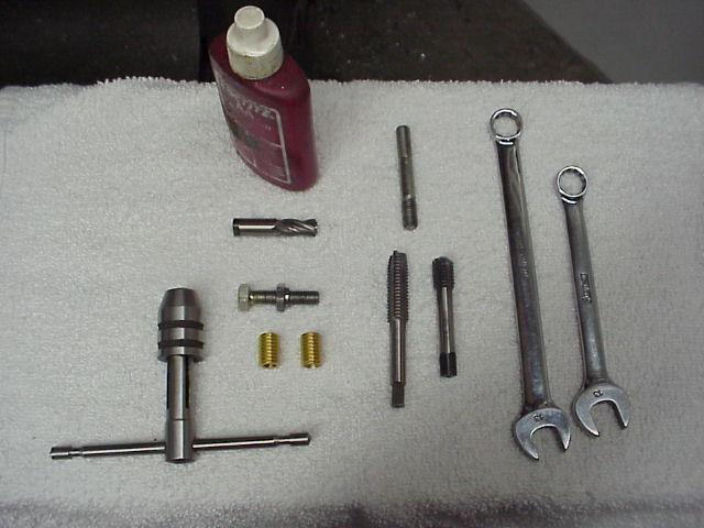
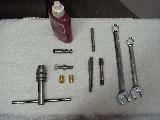
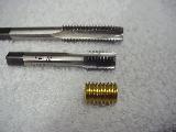
The [hand] tools required are shown at left.
You will need a 4-flute 3/8" endmill, a couple of 7/16" x 14 taps, two 13mm wrenches, an 8mm stud, and some Loctite. You will also need an 8mm thread bolt, and an 8mm nut that is slightly modified. (more on that in a bit) |
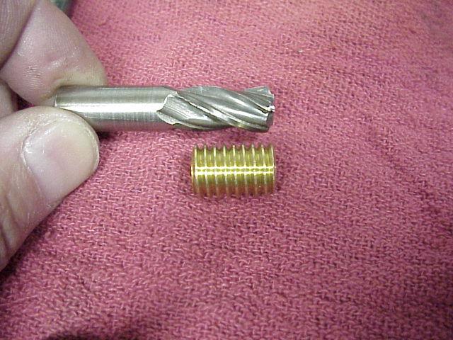
| A single-ended 4-flute 3/8" endmill works best for "drilling" the hole in preparation for tapping. The reason for using a 4-flute endmill is because it is much stiffer than any drill and will not deflect off-center when encountering an irregular hole and/or some of the cast iron from the cylinder liner. Make sure that the endmill has a flute length at least as long as the insert. |
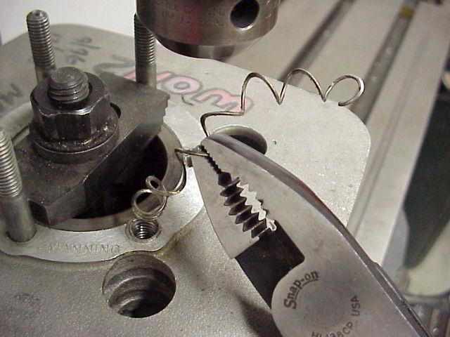
| When tapping the hole, it's best to start with a "taper" tap, and then finish off the threads with a bottoming tap. As you can see in this photo, I simply cut and ground an old (normal length) tap and turned it into a short, bottoming tap. I ground the tap to the same length as the insert as a simple visual reference when the hole is tapped deep enough. |
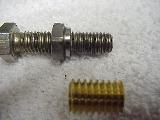
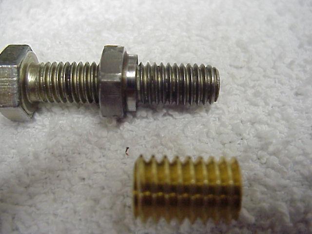
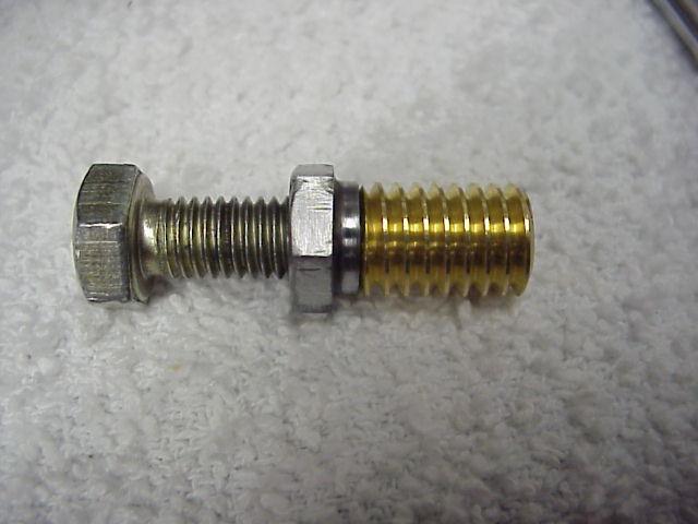
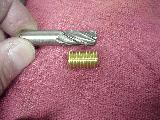
| Here is my insert installation tool. It's simply an 8mm bolt, along with an 8mm nut that has been machined down slightly on one end. |
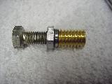 |
Here is the insert ready for installation. As you can see in this photo, having a "stepped" nut will allow you to install the insert at or below flush without any interference. |
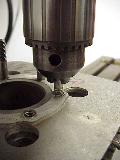 |
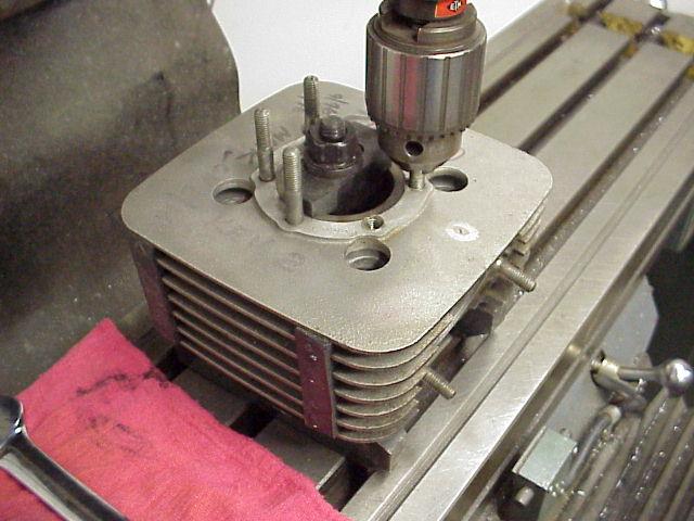
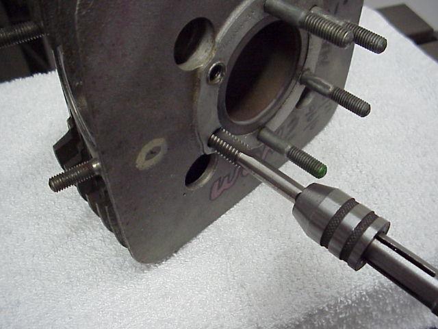
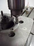
The first step to this job is to line up the spindle of the milling machine directly over the hole to be repaired. I "cheat" a bit to do this: Screw an 8mm stud into the damaged hole (the normal stud that belongs there will work fine). I then chuck the stud (with the cylinder hanging from it) in the drill chuck. I then bring the cylinder down onto a pair of blocks that are taller than the cylinder spigot is long. (visible in next photo) |
 |
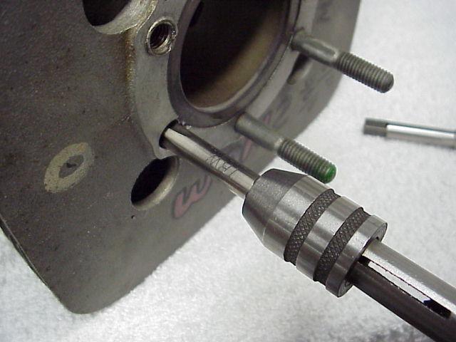
I then go though the bore of the cylinder with a normal 1/2" hold-down stud using a "T-nut" in the table, and a small clamp block at the top that fits down into the head gasket recess on top of the cylinder. The cylinder is "supported" on parallels under the aluminum base -- do not allow the cast iron liner spigot to rest on the table or it might be damaged! Don't forget to clamp down the mill table in both directions so that everything remains lined up over the stud hole. |
 |
Once the cylinder is clamped down solid, you can turn the spindle backwards by hand to remove the stud from the [damaged] threaded hole. IMPORTANT: If this stud hole has been previously repaired with a heli-coil, don't forget to remove it! |
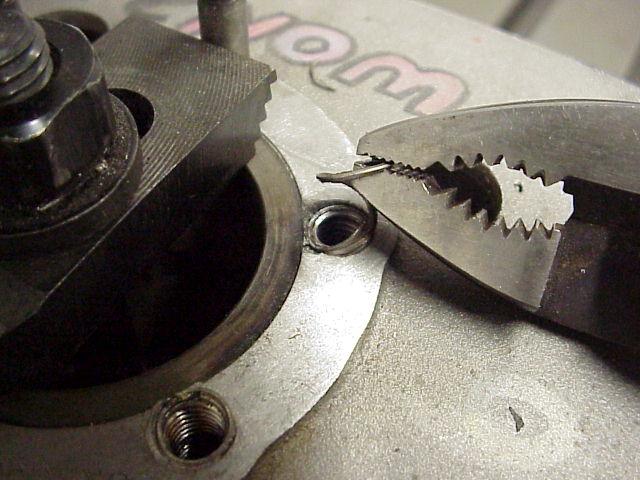
 |
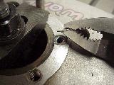
Make sure you get ALL of the heli-coil out of the hole. Most of the time, they will come out intact if you use some care when removing it. |
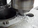 |
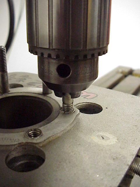
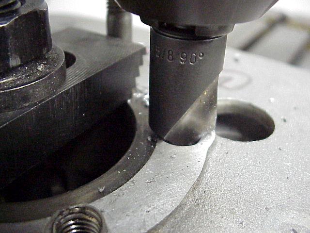
I have chucked up the 3/8" endmill and am using it to "drill" the hole in preparation for tapping. The flute length on the endmill is just longer than the insert so I have a good visual reference on the depth required. USE CAUTION ON THE DEPTH! If you go too deep on a Yamaha cylinder, you may break through the edge of the exhaust port!
Note that I've chucked the endmill very short for maximum stiffness. |
 |
To do a nice job, you'll want to use a 90 degree countersink to chamfer the top surface a bit. |
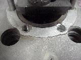 |
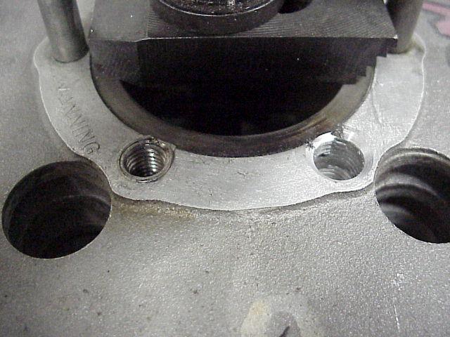
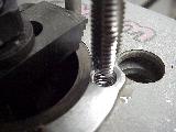
The stud hole on the right is now ready to be tapped 7/16" x 14. As you can see in this photo, part of the cast-iron liner intrudes into the hole a bit. This is the reason for using an endmill instead of a drill: a straight, round hole is the result. |
 |
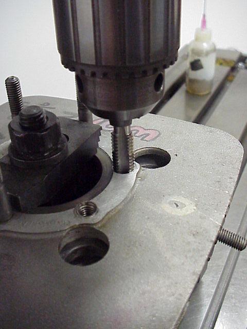
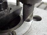
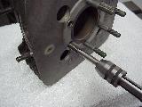
I have now chucked the 7/16" x 14 "taper" tap, and am using the spindle of the milling machine to get it started nice and straight. USE CAUTION if running in the tap under power. If you are at all unsure about doing this, simply bring the quill of the milling machine down and turn the drill chuck by hand to start the tap for a few turns. |
 |
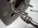
I have now "backed out" the tap from the hole. It is not yet tapped to full depth. I do this by hand with the cylinder out of the machine and sitting on the bench. Note that all the previous steps were done without moving the milling machine table. This insures that the insert will be in the exact same location as the original thread. |
 |
The first step here is to use the "taper" tap that was just used in the milling machine and run it down by hand until it bottoms. |
 |
Now I'm using the reground "bottoming" tap. As you'll recall from the photo showing the tap at the beginning of this article, the tap has been ground to the same length as the insert. As you can see, I've gone maybe 1 or 2 turns past the end of the threads on the tap, which will insure that I'll be able to install the insert at or below flush. |
 |
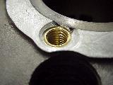
Here is the threaded hole ready for installation of the insert. Clean it thoroughly with something like acetone or carb cleaner since you'll be using Loctite. |
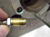 |
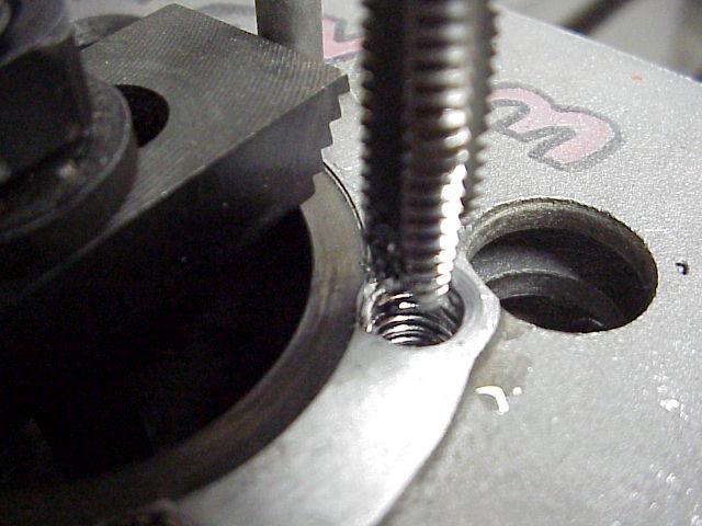
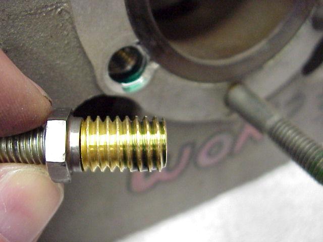
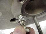
Here's the insert on the installation bolt. I've already applied Loctite to the insert and the threaded hole. I'm not a fan of Loctite, but I use Green Loctite in this application because there is no reason that the insert will ever be removed.
Make sure your installation bolt does not protrude out the end of the insert, as this would prevent the insert from being installed to full depth. |
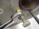 |
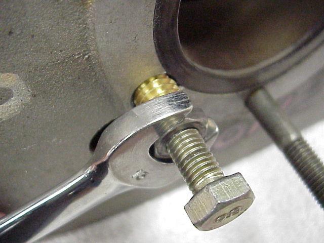
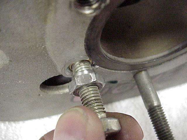
You should be able to install the insert at least part way by hand. When it starts to get a bit tight, use a wrench on the nut, NOT on the head of the bolt. |
 |
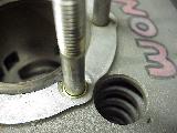
Keep turning on the nut until the insert is below flush. If you've modified the nut on the installation bolt similar to mine, you should be able to get the insert a turn or more below flush before the hex on the nut bottoms against the aluminum on the cylinder. |
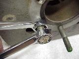 |
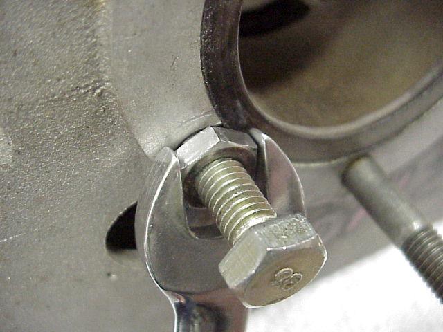
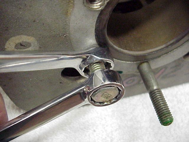
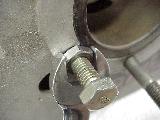
To remove the installation tool from the insert, you'll need to hold the head of the bolt with one wrench, and then crack the nut loose from the top of the insert with another wrench. |
 |
Once you've done that, you'll be able to spin the bolt out of the insert by hand. |
 |
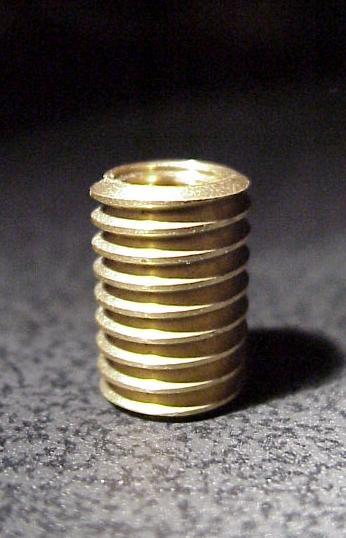
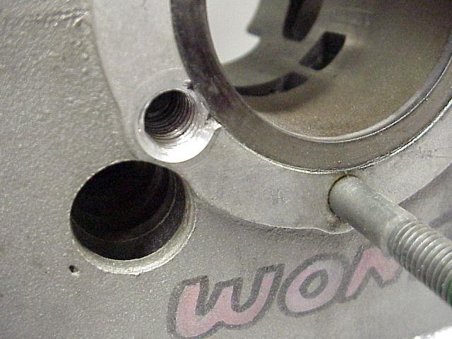
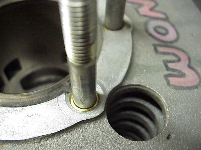
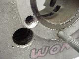
And here is the fully installed insert. Perfect!
If done correctly, this repair will outlast the life of the cylinder.
I recommend letting the cylinder sit overnight to make sure the Loctite is fully "kicked off". Of course you may want to repair the other stud hole now if you're repairing both of them. |
 |
Finally, reinstall the stud back into the repaired hole. DO NOT use Loctite on the stud. Simply put a drop of oil on the stud and screw it in until it bottoms. |